CCNP SWITCH (retake)

Well one more update. I have just checked my email and it seems that CISCO have responded to my comments about the SWITCH exam, and provided me with a re-sit voucher!

I think this says something about the quality of this exam as this is the second voucher I have received. The first was after the exam crashed on me. So hats of to CISCO for that. But this time no excuses, I still don’t think the course material if fit for its purpose, and does not really prepare you for the exam. But having sat it twice, I can’t claim I don’t know the focus, or where my weaknesses lay.

So my intention is to start my new job, get hold of some lab equipment and do some hard studying on the topics I need to. Then I think I should be able to pass this no problem. I did notice the First chapter of the ROUTE foundation seems to cover some of the planning topics nicely so I might flick through it a little more to see if there are any other relevant bits.

DevilWAH

CCNP SWITCH update

Well no luck I’m afraid 🙁

I agree with many of the other complaints about this exam, there seems to be a large number of questions that are not covered in the course material. I say that having read the foundation guide, cert guide, flash cards, and quick reference sheets.

CISCO have now made a statement that due to the high levels of complaints they will be reviewing the exam. So rather than wast time trying to pass it again. I will carry on my studies with the ROUTE course, which has had much better reviews, and come back to the SWITCH. Hopfuly by then CISCO will have sorted out the issues.

DevilWAH

Time up!

Well a night of study and now its to bed for some sleep before my CCNP SWITCH exam.

Hopefully by the time of my next post I will be one third of the way towards achieving my CCNP.

If I’m honest I have not been impressed with the Cisco Press books, or the BOSON test exam, both I have found many errors in. (Hopefully the fact I spot the errors means I understand the topics)

But all going well I will be back with a little something on getting the CISCO SDM to work in Linux soon.

Trouble shooting with ACL’s

We all know of ACL’s for use in restricting traffic when applied to an interface, and also for classing traffic such as when used in NAT to chose the ranges to apply NATing to. But they can also be very useful in trouble shooting you network, and the last few days brought this back to me.

It all started with what seemed like a simple problem. On one of my networks the DHCP helper function had stopped working, and clients could no longer get an IP address. However a quick check of he DHCP server and a glance over the config on the network devices and it all seemed fine.

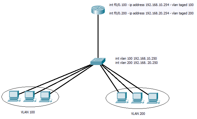
Now the set up is quite simple, your standard basic router on a stick set up. With a CISCO 1841 as the router, which as well as working as the router also is set up as one of the network firewalls. With one interface pointing to the internet (not shown) and the other to the internal network.


FIG 1

We can imagen that the DHCP server is sitting in VLAN 200 and the clients that have stopped working are in VLAN 100. So what’s going on?

Well first move was to look at the DHCP logs on the server to see any sign of requests eing received. Nothing there suggesting the packets whegetting stopped before they gotthere.

Check the router config for the “ip-helper” command. This all looked fine and a quick ping from the router to the DHCP server shows that there is not issue with the router forwarding packets to it. Net step ping the Client PC from the router….. OK here’s an issue router can’t ping the Client? But the client can reach the internet through the router? And stranger still the Client CAN ping the router interface of  192.168.10.254??

To bypass any other part of the network, I set up two SVI on vlan 100 and 200 on the switch directly connected to the router and checked the trunk was carrying both. Again the switch could ping both the interface on the router, but the router could only ping the IP address assigned to the SVI for vlan 200?

Well the first step was to work out if the router was indeed sending a packet out, as I mentioned the Router also acts as a fire wall so could a policy update be causing the issue?

Here is the first use for ACL’s in trouble shooting. Debug commands in cisco are very useful as we know, and one I have used often is the “debug ip packet detail”. But before you go typing it in to a router to test, be aware it will have a massive hit on the CPU and you will be over whelmed with information as the detail of every packet crossing your router is displayed to you.

Before you start debugging create an access list that will permit all the traffic you are interested in. In this case I only want to see traffic to and from 192.168.10.254, so logging on the the router create the access list.

ip acccess-list extended 150

permit ip any host 192.168.10.254

permit ip host 192.168.10.254 any

Then you can run the debug command and only view the details about packets covered by this access list.

debug ip packets 150 detail

Enabling this on the Router and again pinging the 192.168.10.250 address and the debug output show the packets sent out on vlan 100, and to be sure enabling the same debug on the switch and I could see the packets both received from the router and being sent back out the same vlan interface. Yet the router logs show no sign of packets getting dropped or even being received. Neither dose this debug show any sign of the packets this is not surprising as debugging IP packets shows packets that are crossing the control plane of the router and if an  ACL or the fire wall are blocking them they will not reach this.

So here is the next use for a ACL in trouble shooting. One of the first steps a packet takes when received on an interface is getting checked by any applied ACL. This is a reasonable step as for security reasons you want to drop any rogue packets ASAP.  So by creating adding the line “permit ip any any” to the end of the above ACL, and the command “log” to the first two line. I then applied this ACL to the interface in the inward direction.

Now repeating the ping to 192.168.10.250 from the router and I see in the logs packets being transmitted and getting received. Now I know that the issue is with in the firewall policy’s on the router.

So yes ACL’s are not only great for security and for managing live data flows across the network. But they are also useful in trouble shooting, especially when used to filter outputs of show and debug commands to  useful information. And using the log function you can capture sporadic issues with out having to be logged on the whole time watching for it.

DevilWAH

PS. There is also the “debug packet” command to capture traffic received on an interface, but I like the simplicity and logging ability of using an ACL.

QoS and leaky Buckets

Just been going through QoS in the foundation guide, it has a small bit on the Leaky bucket algorithm, but I think the wikipedia article explains in much clearer.

I had always though of it as the packets where the water running in to the bucket and there was a small hole in the bottom from which it drained out. As long as the average in was less than the drainage hole, and bursting did not over flow the bucket the water flows out with out spilling.

However I see now that in the case of CISCO switches the leaky bucket is a metering method. The packet it self does not flow in to the bucket. Rather how fast the packets flow in to the switch determines how fast the tap above the bucket it flowing. While the bucket it not full the packets can pass through the switch. But if the bucket should over flow the packets are dropped until enough water has run out of the bucket that they can continue.

Like I said the article on wikipedia explains it all very nicely, so if like me it is taking a bit to get your head around have a look.

DevilWAH

Setting up HSRP (or how not to..)

OK need time out from reading about wireless networks, its all a bit of a repeat to be honest and I’m getting brain ache. I have update my ANKI flashcard pack though with some of it.

But I thought a few words on HSRP would help clear my mind.

HSRP (hot spare routing protocol), its a wonderful idea of CISCO’s. Two or more Routers on a subnet, sharing one IP address. You assign you client PC’s this IP as there default gate way, and in the event of one of the routers failing another takes over and keeps connectivity for you clients! And so simply to set up (both cisco routers and switches with the advanced IP feature set have this).

On the Primary router enter the config mode followed by the interface you wish to configure this on, and enter the following commands

(config-if)#ip address 192.168.14.200 255.255.255.0
(config-if)#standby 1 preempt
(config-if)#standby 1 ip 192.168.14.254
(config-if)#standby 1 priority 100

Then on the secondary router enter the following.

(config-if)#ip address 192.168.14.100 255.255.255.0
(config-if)#standby 1 preempt
(config-if)#standby 1 ip 192.168.14.254
(config-if)#standby 1 priority 95

And there we have it, now the first router will respond to any ARP requests for the 192.168.14.254 address which can be used as the DFGW for you clients. What is even better is that the routers will share the same MAC address for this IP. So in the event of the primary router failing with in 3 seconds (default timers) the secondry router takes over and all currently active clients will be able to carry on where they left off.

As always that is far from all you can do with HSRP, one of the main limitation you may notice is only one gateway is active at any one time, and although you can play with HSRP to achieve load balancing (See here), there is a much better way by using GLBP (Gateway Load Balancing Protocol). You can also have HSRP track interfaces and IP SLA counters to increase and decrease a routers priority to insure the router in the best position is running as the active, this cisco document covers the settings in far more detail than there is space for here.

Now for the how not to do it part 😉

By default the timers on HSRP are set to send a hello every 1 second and the standby router becomes active if it fails to hear a hello from the active route for more than 3 seconds. you don’t have to enter this of couse but the command would like like this to set it up

(config-if)#standby 1 timers 1 3

But 3 seconds ????!!!!!!!!!!!! three second network outage I cried! Hitting the question mark after typing (config-if)#standby 1 timers ?… what’s this I see msec. Yay I cried and after checking the documentation so see this really did reduce timers to the msec range, I proceeded to configure a hello timer of 50msec and a hold timer of 150msec ( you can actual configure it as low as 10msec). A quick test and yes almost instance fail over, not even a packet dropped, and I went home a happy lad.

However I configured that in the evening with little traffic on the network, next day just before lunch however…. Oh this is not so good, no one can get out of site? Things start to move then crash to a stop again. Well better log on to the core switches I suppose and see what the logs are saying….. Umm nope they wont let me on just hanging. Finally after switching off the secondary switch the primary one magically let me log in again and after checking its logs I could see what was happening. With such short hello timers packets where getting dropped, the switches started flapping between active and standby and in doing so just made the issue worse. And they could not settle on who was in charge.

From this I learnt two important things, First the don’t go below 200msec hello timers and 700msec hold timers (come on still less than a second fail over), and only do this is the routers/switches are directly attached. Secondly add in a preempt delay statement

(config-if)#standby 1 preempt delay 10

This will stop the flapping between active and standby. Once a device has change state away from being the active router, with the configuration above it must wait at least 10 seconds before it can take over again.

And finally just because you can do some thing does not mean you should or need to. The time out in the TCP stack in XP (and most other systems) is at least 9 seconds. In the case of VoIP and Video a few seconds delay may make a call hicup, but it will normally stay up. And people will not mine or take much notice of a slight hicup as long as it only happens once ever 6 months.

There are cases when you need better fail times, in which case you need the correct equipment. HSRP is a great technology but as I found back a few years ago when I did this. You can push a good thing to far.

For those of you with out CISCO devices, the industry standard version is VRRP (Virtual Router Redundancy Protocol), and some information on that can be found in this document.

Well I hope some of you will learn from my mistake, thankfully because I had played around with HSRP a lot on a test network, I was in a good position to trouble shoot and had it back up and working quickly. But still it is one of the times few times I have had to hold up my hands to management. Thank fully these times are rare and so far non-critical and short lived…

Well back to work tomorrow. Night all have a good one.

Tree’s that Span the network

Lets start with a few links.

Cisco’s introduction to STP.

Cisco’s configuration guide

Before I learnt about sub-netting, trunk links, access ports, or vlan’s, I started looking in to STP. In fact my introduction to networking went along the lines of. Learn to log on to a 3COM 3300 super stack, assign it an IP address, sort out spanning tree. I had only been working in IT a few months with no previous IT experience when I was given the job of single handily auditing the network and assigning management IP address.  At the time the network was a pure Layer 2 single VLAN domain containing around 120 switches spread over 30 buildings. It was during this audit and while setting up a monitoring system that I first notice these network reconfiguration messages that kept popping up, not one to be able to leave alone I looked in to the cause and discovered STP!

I look back on horror as I dread to think how many of those reconfiguration where due to me rebooting a switch, or altering configs. those 3COM’s only ran old CST (802.1d) so every time I was causing up to 50 seconds of down time.. I can only plead ignorance and hope over the past 4 years I have made up for it.

The Spanning Tree Protocol (STP) I think is at its fundamental core, one of the more straight forward networking topics to understand. STP runs at layer 2 and its core function is to prevent loops in the network. Why do we need to prevent loops? Layer 2 has no default inbuilt method to detect if a switch has forwarded the same frame before, so if there are any cabling loops in the network frames will circle endlessly round them, clogging up bandwidth and switch CPU causing poor performance before it all grinds to a halt. At the same time though surely duplicate links are a good thing, if one fails you have one spare?

And this is where all versions of STP come along, by analysing the network as a whole, by sending special packets (bridge discover protocol units BPDU’s)  along every link of the network and seeing where the end up, the switches can detect any loops. They will then decided on which links to “block” so that there is only a single complete path across the network. And of course they have there methods to bring back up any of the blocked links in the event any of the primary links they back up should fail.

Before we get in to how this work lets recap the various versions of STP.

CST = 802.1d = Low =SLOW
PVST+ = CISCO = High = SLOW (default)
RSTP = 802.1w = Medium = FAST
PVRST = CISCO = Very High = FAST
MSTP = 802.1s = Medium/High = FAST

Lets start with PVST+, This differers from CST only in that it runs a separate instance for each VLAN on the switch, this allows load balancing or backup links as we shall see.  First lets get a digram up so we have some thing to refer to.
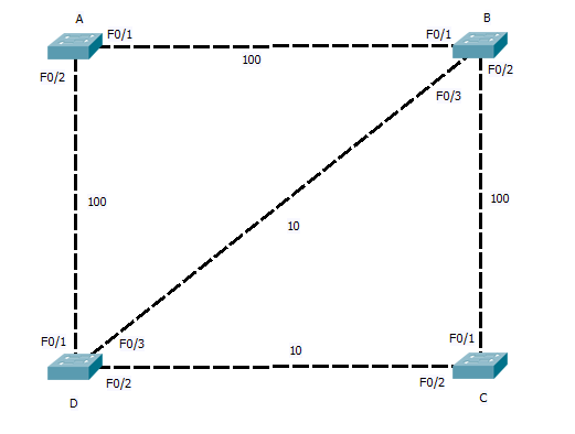
STP works by each switch determining which of its own ports should be forwarding and which should be blocking to insure the network is loop free. Because this is carry out in isolation of what ports other switches and to reduce the time and traffic the network administrator selects a central switch (the ROOT bridge) to act as a reference point for all the other switches. This central switch sends out packets (BPDU’s) on all its ports that are connected. As other switches receive these they note on what ports they are received and then add on the cost of the link. This cost is based on the speed of the link, the following is the table of defaults but these can be tuned if needed.

10Mbs =100
100Mbs = 19
1Gbs = 4
10Gbs = 2

So our fist step should be to configure what switch is root. This should be your core switch, as this will become the centre of the network with all other switches sending there traffic through it. In the case above we can used Switch A.

Switch_A(config)#spanning tree mode pvst
Switch_A(config)#spanning tree VLAN <ID> root Primary

All done…

Switch A is now the root bridge for the spanning tree on what ever VLAN ID you enter. The keyword root will cause Switch A to listen out on the network for BPDU’s being advertised on the VLAN, each switch advertise its root priority in its BPDU. Switch A will listen for the lowest and then set its own priority lower again. (lowest wins). This only happens as you enter the command. If at a later time another switch is set to a lower priority this switch will take over the root, Switch A will NOT lower its priority again. For this reason there are things like Root Guard that can be enabled.

At the moment the network digram still has loops so how does STP sort it out? Fist of all, ALL ports on A will be in the forwarding state (unblocked), and it is sending out BPDU’s. So lets see how Switch B figures it all out. First it receives a BPDU from Switch A on port F0/1, this has come in over a 100>bs link so it is given a cost of 19, the BPDU on port F0/2 has come via switch D, this will have added a cost of 19 is self as it received it, and Switch B will add a further cost of 100, giving a total root cost of F0/2 as 119. Working the same way F0/3 will be 19 + 100 + 19 = 138.

So the as the lowest cost port becomes the root back to port, Switch B will assign F0/1 as the root port. Repeat for switches C and D, and you will find, for switch C the root port is  F0/1 with a cost of 38 and for Switch D it is F0/1 with a cost of 19.

And what now? well now the root ports are sorted out we need to move on to designated ports. These are ports that are connected upstream pointing away from the root. With Switch B and D we see there is a stale mate, both have a 100Mbs link to the root and are connected together by a 10Mbs link. Next STP look towards port priority and as this is the same (both using same port ID) it looks to the MAC address. We will assume Switch B has the lower mac and so it has the higher priority). Switch B will there for place its port F0/3 in to a designated state, Switch D on the other hand seeing Switch B is higher Priority will leave its port with out a STP state.  Both Switch B and D will place ports F0/2 that connect to switch C in to the designated state. Switch C already having a root port to B, and seeing that port F0/2 also leads back to the root will again leave this port in a non designated state.

Once the Switches have decided what ports are assigned what states, any port still with out a state and that is receiving the Root BPDU, is put in the blocking state. So we end up with the logical network below.
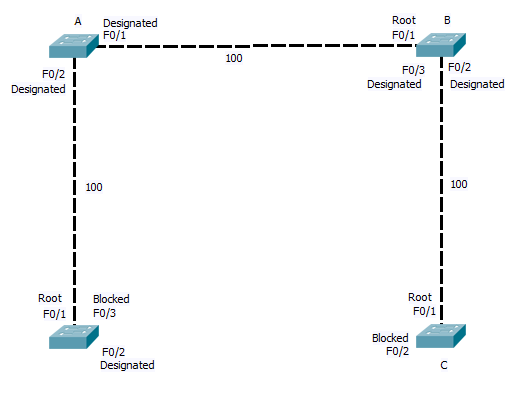
As you can see where a link is blocked, one end will be in the designated state on one in the blocking state. In the case of CST and PVST, all BPDU’s are send from the root bridge. In the event of a link failure the affected switch must wait for the Root bridge to send out a BPDU (20 seconds time out by default), Only then does the switch start to listen for BPDU’s on its blocked ports before bringing them up. and this process in its self requires 15 seconds in the listing phase (listing out for the BPDU and building the STP) and a further 15 seconds of learning MAC address before the switch is again forwarding traffic across the back up link. So a total of 50 seconds can elapse.

RSTP and PVRSTP, address this issue, By allowing all switchs in the STP to send and recive BPDU’s, and keeping a note of what are the back up links that are currently being blocked, RSTP and PVRSTP can bring up a failed link with in a second or two. They introduce two new port states. The backup port, which is a second link back to the root. (in the network digram here port F0/3 on switch D and F0/2 on C would be back up ports) And the alternative port, this is when two links connect to the same uplink switch, Imagen switch B and C has two links directly between them, then one would be in the designated port state and the other blocked in the alternative state. By holing a note of the back up links, if the link between Switch D and the root failed, it knows it can bring the link on port F0/3 to switch B up with out danger of causing a loop.

So that’s STP in a nutshell, I will cover MSTP another day, but hopefully there’s enough there to get you head round it, with out load of configuration. All you need to remember is to define your root bridges correctly and insure all you switches are using and support the same STP mode. Once you have that configured correctly then STP will work for you. You then can spend the time tuning it and securing it. Which is a whole other post.

CCNP SWITCH CERT Updates

Those of you doing you switch exam my be interested to read these. Some updates to the CCNP SWITCH cert guide have been released. It looks like they cover some the the Planning topics, and also in there is some SVI stuff.

There has been a lot of discussion over CISCO’s handling of the planing part of this exam, so hopefully this extra material will help clear it up. Having glanced though it I remain to be convinced, but I will reserve full judgement till later.

Enjoy the read and will be back later with a new CCNP topic to review.

Filtering the VLAN Traffic

So it ended up I decided to do a recap on VLAN access control lists (ACL’s) before I got back into Spanning Tree. I also covered Private VLAN’s tonight but will come back to them some other time for the blog.

Over the years I have had lots of dealing with port and router based ACL’s, but VLAN based ACL’s I only came across when I started studying for my CCNP. And I already have plans to use them to limit the traffic on some of our more sensitive network segments.

Now if you know you VACL set up, here is the point to stop reading, what follows is a run through of the config, with some description of the steps.

Still with me? OK lets get to it.

The first step in creating a VACL’s is in fact to create some “standard” ACL’s first, these will be used to classify what traffic is filtered once the VACL is applied. the VACL will accept two types of access lists as arguments IP and MAC, so lets set some up.

(config)#access-list 100 permit ip host 172.168.5.5 any

(config)#mac access-list extended MAC-ACL
(config-ext-mac)#permit any host b7d4.5f6d.8e31

So two simple ACL’s created, now you can you the IP access list command and create named access lists as will if you wish.

So now we need to create the VACL and add these lists to it.

(config)#vlan access-map <name> 10
(config-map)#match ip address 100
(config-map)#action drop
(config-map)#vlan access-map <name> 20
(config-map)#match mac-address MAC-ACL
(config-map)#action drop
(config-map)#vlan access-map <name>30
(config-map)#action forward

Notice by default if a VACL is configured on a VLAN is a packet does not match the VACL it will be dropped. As we can see each section in the VACL has a sequence number, a match statement (can have more than one) and an action to take. In this set up any traffic that matches the two ACL’s we set up will be dropped. By adding a sequence with out any match statement and only an action, we have set up a “catch all”  situation, just like you may do with a “standard ACL when you enter “permit any any”.

So there we have it the VACL all set up and ready to go, now its just a case of applying it to a VLAN or two.

(config)#vlan filter <name> vlan-list 10

And there you have it, now any traffic passing across the switch on the configured VLAN’s will be subject to the statements in you VACL. I think there great for adding that extra layer of security to your network, and keeping traffic where it should be.

OK so not an exciting post tonight, but I will get back to STP tomorrow and I can tell you from past experience how not to configure it.

Night all and take care.