TED Ideas Worth Spreading

I have had this site in my book marks for ages, but only today have I had a proper look in to it. IT is a non profit organisation who have got together with many world leaders in the fields of science, technology, politics, business and more to produce hundreds of short videos on there chosen field. (How about learn what the higgs boson partical is in 10 minutes, as well as see the ultimate formula that describes the whole universe written on a single page here! I do like my physic)

TED Ideas Worth Sharing

Defiantly a good site for the lunch time bookmarks.

Enjoy

DevilWAH

I had to come bacck and post this video from the site.

The Beauty  of data Visualisation

And for thoses of you interested in news then you might like this page, this one kind of leads on from the video above.

Newsmap

The Four Classes of Socity

Time from some light entertainment… Which class are you?

I am a Geek

One of four titles used to classify someone based on their technical and social skills. The other three titles are nerd, dork, and normie. The difference between the four titles can be easily shown in table form:

Title Tec Skills Social Skills
Nomie No Yes
Geek Yes Yes
Nerd Yes No
Dork No No

Normie: A normal person. Blah.

Geek: An outwardly normal person who has taken the time to learn technical skills. Geeks have as normal a social life as anyone, and usually the only way to tell if someone is a geek is if they inform you of their skills.

Nerd: A socially awkward person who has learned technical skills due to the spare time they enjoy from being generally neglected. Their technical knowledge then leads normies to neglect them even further, leading to more development of their technical skills, more neglection, etc. This vicious cycle drives them even more into social oblivion.

Dork: A person who, although also socially awkward, doesn’t have the intelligence to fill the void with technical pursuits, like a nerd, and is forced to do mindless activities. Almost always alone. Usually with an XBox. Like playing Halo. All day. Every day. Not even understanding how the Xbox is making the pretty pictures on the screen. Very sad.

(Now forgive me I forget where I picked this up, But if any one knows the original author please let me know so I can give credit where it is due. )

Setting up HSRP (or how not to..)

OK need time out from reading about wireless networks, its all a bit of a repeat to be honest and I’m getting brain ache. I have update my ANKI flashcard pack though with some of it.

But I thought a few words on HSRP would help clear my mind.

HSRP (hot spare routing protocol), its a wonderful idea of CISCO’s. Two or more Routers on a subnet, sharing one IP address. You assign you client PC’s this IP as there default gate way, and in the event of one of the routers failing another takes over and keeps connectivity for you clients! And so simply to set up (both cisco routers and switches with the advanced IP feature set have this).

On the Primary router enter the config mode followed by the interface you wish to configure this on, and enter the following commands

(config-if)#ip address 192.168.14.200 255.255.255.0
(config-if)#standby 1 preempt
(config-if)#standby 1 ip 192.168.14.254
(config-if)#standby 1 priority 100

Then on the secondary router enter the following.

(config-if)#ip address 192.168.14.100 255.255.255.0
(config-if)#standby 1 preempt
(config-if)#standby 1 ip 192.168.14.254
(config-if)#standby 1 priority 95

And there we have it, now the first router will respond to any ARP requests for the 192.168.14.254 address which can be used as the DFGW for you clients. What is even better is that the routers will share the same MAC address for this IP. So in the event of the primary router failing with in 3 seconds (default timers) the secondry router takes over and all currently active clients will be able to carry on where they left off.

As always that is far from all you can do with HSRP, one of the main limitation you may notice is only one gateway is active at any one time, and although you can play with HSRP to achieve load balancing (See here), there is a much better way by using GLBP (Gateway Load Balancing Protocol). You can also have HSRP track interfaces and IP SLA counters to increase and decrease a routers priority to insure the router in the best position is running as the active, this cisco document covers the settings in far more detail than there is space for here.

Now for the how not to do it part 😉

By default the timers on HSRP are set to send a hello every 1 second and the standby router becomes active if it fails to hear a hello from the active route for more than 3 seconds. you don’t have to enter this of couse but the command would like like this to set it up

(config-if)#standby 1 timers 1 3

But 3 seconds ????!!!!!!!!!!!! three second network outage I cried! Hitting the question mark after typing (config-if)#standby 1 timers ?… what’s this I see msec. Yay I cried and after checking the documentation so see this really did reduce timers to the msec range, I proceeded to configure a hello timer of 50msec and a hold timer of 150msec ( you can actual configure it as low as 10msec). A quick test and yes almost instance fail over, not even a packet dropped, and I went home a happy lad.

However I configured that in the evening with little traffic on the network, next day just before lunch however…. Oh this is not so good, no one can get out of site? Things start to move then crash to a stop again. Well better log on to the core switches I suppose and see what the logs are saying….. Umm nope they wont let me on just hanging. Finally after switching off the secondary switch the primary one magically let me log in again and after checking its logs I could see what was happening. With such short hello timers packets where getting dropped, the switches started flapping between active and standby and in doing so just made the issue worse. And they could not settle on who was in charge.

From this I learnt two important things, First the don’t go below 200msec hello timers and 700msec hold timers (come on still less than a second fail over), and only do this is the routers/switches are directly attached. Secondly add in a preempt delay statement

(config-if)#standby 1 preempt delay 10

This will stop the flapping between active and standby. Once a device has change state away from being the active router, with the configuration above it must wait at least 10 seconds before it can take over again.

And finally just because you can do some thing does not mean you should or need to. The time out in the TCP stack in XP (and most other systems) is at least 9 seconds. In the case of VoIP and Video a few seconds delay may make a call hicup, but it will normally stay up. And people will not mine or take much notice of a slight hicup as long as it only happens once ever 6 months.

There are cases when you need better fail times, in which case you need the correct equipment. HSRP is a great technology but as I found back a few years ago when I did this. You can push a good thing to far.

For those of you with out CISCO devices, the industry standard version is VRRP (Virtual Router Redundancy Protocol), and some information on that can be found in this document.

Well I hope some of you will learn from my mistake, thankfully because I had played around with HSRP a lot on a test network, I was in a good position to trouble shoot and had it back up and working quickly. But still it is one of the times few times I have had to hold up my hands to management. Thank fully these times are rare and so far non-critical and short lived…

Well back to work tomorrow. Night all have a good one.

Site URL update.

I have just the blog to a new directory on the web page, hopefully I have caught all the link errors, but if you see any broken links please let me know.

Ahh the site cache caught me out there, it seems more links than I thought where broken, however with the help of a few link checking sites and a nice helpful plug in I am hoping they are all fixed now.

Cheers

SSH port Forwarding (or how to Remote Desktop over SSH)

I found this one out quite recently, but wish I had come across it years ago.

Image you have SSH access to a device inside a remote network, what you really want is a remote desktop to a device inside, but firewalls are blocking RDP and you have no way to change there setting (maybe you need to be on the desktop to configure the firewalls?)

Well as long as you can meet the two basic requirements below then fear not, because another of SSH’s little tricks is to allow you to tunnel traffic over it.

  1. First you must have a SSH client on your local station that can carry out port forwarding. such as Putty or Teraterm.
  2. An SSH remote client that is allowed to send traffic on the RDP ports to the final end station you want to remote desktop to.

All set then lets go..

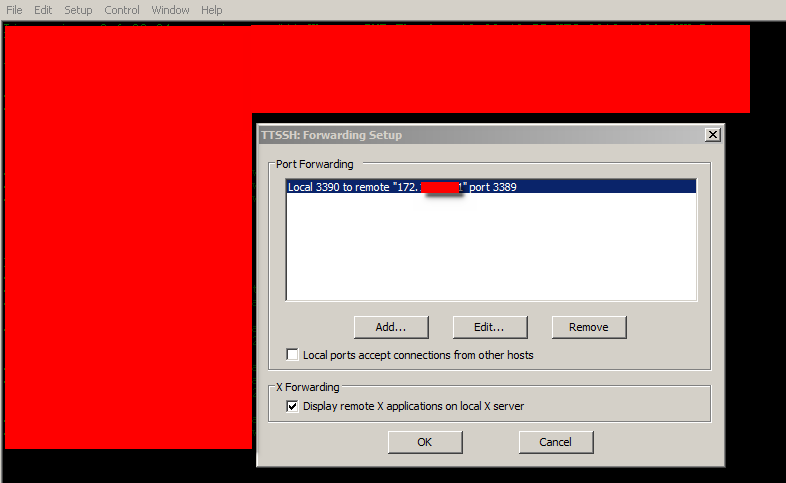
First you need to set up the local telnet client. Here I will show it with Tera Term, as its the one I have installed, but the settings for putty and others are straight forward to match. What we are doing is mapping a local IP and port for Tera term to catch data sent to, and then relay it across the SSH connection to the remote SSH client where it will be forwarded on to the destination remote desktop client using the IP and Port set up.

First open up Tera Term and chose Setup then SSH forwarding from the menu, once the box pops up chose add. For the local forwarding port you can chose any random valid port, for this example I will use 3390. For the remote IP enter the IP of the machine you want to remote desktop to and the RDP port it is set to listen on, by default this is 3389 so we will use this.  (hint if you want to RDP to multiply remote hosts, simple set up a different local port for each one) Click OK and you should have a screen something like below.

Now click on the OK button.

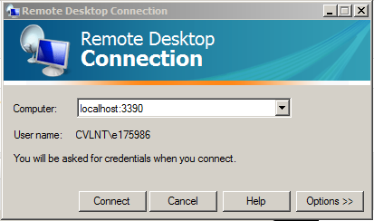
The final steps are easy, in Tera Term click on file new connection, and connect up an SSH session to the SSH remote host as you normally would. While this connection is active open up the RDP client on the local host and enter the computer to connect to as shown.

Note the use of the Local port we configured above. Clicking on connect, Tera Term will now tunnel the traffic over the SSH connection where it will be forwarded on to the remote desktop host.

Yes you can achieve a more user friendly set up using VPN’s and I would not suggested it for end users. But I have found this very helpful in admin situation. And your remote SSH client can be any thing that supports SSH, Linux box or Cisco device all work just great.

Well hope you have all had a great Saturday and have good things to look forward to tommorrow.

Night from the Devil.

Tree’s that Span the network

Lets start with a few links.

Cisco’s introduction to STP.

Cisco’s configuration guide

Before I learnt about sub-netting, trunk links, access ports, or vlan’s, I started looking in to STP. In fact my introduction to networking went along the lines of. Learn to log on to a 3COM 3300 super stack, assign it an IP address, sort out spanning tree. I had only been working in IT a few months with no previous IT experience when I was given the job of single handily auditing the network and assigning management IP address.  At the time the network was a pure Layer 2 single VLAN domain containing around 120 switches spread over 30 buildings. It was during this audit and while setting up a monitoring system that I first notice these network reconfiguration messages that kept popping up, not one to be able to leave alone I looked in to the cause and discovered STP!

I look back on horror as I dread to think how many of those reconfiguration where due to me rebooting a switch, or altering configs. those 3COM’s only ran old CST (802.1d) so every time I was causing up to 50 seconds of down time.. I can only plead ignorance and hope over the past 4 years I have made up for it.

The Spanning Tree Protocol (STP) I think is at its fundamental core, one of the more straight forward networking topics to understand. STP runs at layer 2 and its core function is to prevent loops in the network. Why do we need to prevent loops? Layer 2 has no default inbuilt method to detect if a switch has forwarded the same frame before, so if there are any cabling loops in the network frames will circle endlessly round them, clogging up bandwidth and switch CPU causing poor performance before it all grinds to a halt. At the same time though surely duplicate links are a good thing, if one fails you have one spare?

And this is where all versions of STP come along, by analysing the network as a whole, by sending special packets (bridge discover protocol units BPDU’s)  along every link of the network and seeing where the end up, the switches can detect any loops. They will then decided on which links to “block” so that there is only a single complete path across the network. And of course they have there methods to bring back up any of the blocked links in the event any of the primary links they back up should fail.

Before we get in to how this work lets recap the various versions of STP.

CST = 802.1d = Low =SLOW
PVST+ = CISCO = High = SLOW (default)
RSTP = 802.1w = Medium = FAST
PVRST = CISCO = Very High = FAST
MSTP = 802.1s = Medium/High = FAST

Lets start with PVST+, This differers from CST only in that it runs a separate instance for each VLAN on the switch, this allows load balancing or backup links as we shall see.  First lets get a digram up so we have some thing to refer to.
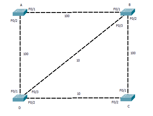
STP works by each switch determining which of its own ports should be forwarding and which should be blocking to insure the network is loop free. Because this is carry out in isolation of what ports other switches and to reduce the time and traffic the network administrator selects a central switch (the ROOT bridge) to act as a reference point for all the other switches. This central switch sends out packets (BPDU’s) on all its ports that are connected. As other switches receive these they note on what ports they are received and then add on the cost of the link. This cost is based on the speed of the link, the following is the table of defaults but these can be tuned if needed.

10Mbs =100
100Mbs = 19
1Gbs = 4
10Gbs = 2

So our fist step should be to configure what switch is root. This should be your core switch, as this will become the centre of the network with all other switches sending there traffic through it. In the case above we can used Switch A.

Switch_A(config)#spanning tree mode pvst
Switch_A(config)#spanning tree VLAN <ID> root Primary

All done…

Switch A is now the root bridge for the spanning tree on what ever VLAN ID you enter. The keyword root will cause Switch A to listen out on the network for BPDU’s being advertised on the VLAN, each switch advertise its root priority in its BPDU. Switch A will listen for the lowest and then set its own priority lower again. (lowest wins). This only happens as you enter the command. If at a later time another switch is set to a lower priority this switch will take over the root, Switch A will NOT lower its priority again. For this reason there are things like Root Guard that can be enabled.

At the moment the network digram still has loops so how does STP sort it out? Fist of all, ALL ports on A will be in the forwarding state (unblocked), and it is sending out BPDU’s. So lets see how Switch B figures it all out. First it receives a BPDU from Switch A on port F0/1, this has come in over a 100>bs link so it is given a cost of 19, the BPDU on port F0/2 has come via switch D, this will have added a cost of 19 is self as it received it, and Switch B will add a further cost of 100, giving a total root cost of F0/2 as 119. Working the same way F0/3 will be 19 + 100 + 19 = 138.

So the as the lowest cost port becomes the root back to port, Switch B will assign F0/1 as the root port. Repeat for switches C and D, and you will find, for switch C the root port is  F0/1 with a cost of 38 and for Switch D it is F0/1 with a cost of 19.

And what now? well now the root ports are sorted out we need to move on to designated ports. These are ports that are connected upstream pointing away from the root. With Switch B and D we see there is a stale mate, both have a 100Mbs link to the root and are connected together by a 10Mbs link. Next STP look towards port priority and as this is the same (both using same port ID) it looks to the MAC address. We will assume Switch B has the lower mac and so it has the higher priority). Switch B will there for place its port F0/3 in to a designated state, Switch D on the other hand seeing Switch B is higher Priority will leave its port with out a STP state.  Both Switch B and D will place ports F0/2 that connect to switch C in to the designated state. Switch C already having a root port to B, and seeing that port F0/2 also leads back to the root will again leave this port in a non designated state.

Once the Switches have decided what ports are assigned what states, any port still with out a state and that is receiving the Root BPDU, is put in the blocking state. So we end up with the logical network below.
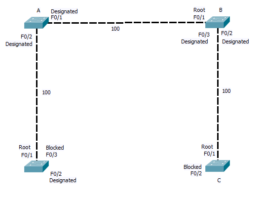
As you can see where a link is blocked, one end will be in the designated state on one in the blocking state. In the case of CST and PVST, all BPDU’s are send from the root bridge. In the event of a link failure the affected switch must wait for the Root bridge to send out a BPDU (20 seconds time out by default), Only then does the switch start to listen for BPDU’s on its blocked ports before bringing them up. and this process in its self requires 15 seconds in the listing phase (listing out for the BPDU and building the STP) and a further 15 seconds of learning MAC address before the switch is again forwarding traffic across the back up link. So a total of 50 seconds can elapse.

RSTP and PVRSTP, address this issue, By allowing all switchs in the STP to send and recive BPDU’s, and keeping a note of what are the back up links that are currently being blocked, RSTP and PVRSTP can bring up a failed link with in a second or two. They introduce two new port states. The backup port, which is a second link back to the root. (in the network digram here port F0/3 on switch D and F0/2 on C would be back up ports) And the alternative port, this is when two links connect to the same uplink switch, Imagen switch B and C has two links directly between them, then one would be in the designated port state and the other blocked in the alternative state. By holing a note of the back up links, if the link between Switch D and the root failed, it knows it can bring the link on port F0/3 to switch B up with out danger of causing a loop.

So that’s STP in a nutshell, I will cover MSTP another day, but hopefully there’s enough there to get you head round it, with out load of configuration. All you need to remember is to define your root bridges correctly and insure all you switches are using and support the same STP mode. Once you have that configured correctly then STP will work for you. You then can spend the time tuning it and securing it. Which is a whole other post.

CCNP SWITCH CERT Updates

Those of you doing you switch exam my be interested to read these. Some updates to the CCNP SWITCH cert guide have been released. It looks like they cover some the the Planning topics, and also in there is some SVI stuff.

There has been a lot of discussion over CISCO’s handling of the planing part of this exam, so hopefully this extra material will help clear it up. Having glanced though it I remain to be convinced, but I will reserve full judgement till later.

Enjoy the read and will be back later with a new CCNP topic to review.

CISCO SDM why oh why oh why!

You would think a company like cisco would be able to produce a management tool that works.

Now I know SDM has issues with different java versions in windows and that in its self seems to be pot luck if it works or not.

But getting it running under Linux, oh my god! every thing sees to be against me here. And the worst thing about it all is how close I can get. I sure its doing this just to tease me.

I have tried old and new Firefox, about 6 versions of JAVA and still no joy. Its time to go home now and no remote access to the firewall so it will have to wait till Tuesday for my next play. So email still not working..

Ah well the weekend ahead, walks with the dogs, and some nice food to look forward to. Oh and of course lots of studying. 😉

Have a great one.

JAVA versions in Linux.

I am still quite a newbie when it comes to Linux, and have a long way to go yet before I could be considered an expert. But slowly I am getting there.

Today to help with setting up the firewall to allow email, I thought it was time I finally got around to installing Java on this PC, and because CISCO SDM express requires an old version this means setting up multiply versions.

Installing the first one is simple enough

$sudo apt-get install java….

(you can do an
$apt-get update
followed by
$apt-cache search java
and this will show you what versions are available for download.)

and after a bit of poking around the second one was simple enough as well, download the bin file from www.JAVA.com and extract it to a directory (this can be any where you want, although the /opt/ one seems to be a common choice) as below. If you want more instructions just click on the instruction link on the site.

$sudo sh ./java-5-4…..

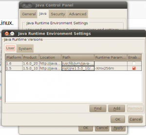
Then cheat and open the java desktop control panel open up the runtime environment settings and add in you new version. (if any Linux masters wan’t to post the guru way to do this please do 🙂 )

And there you have it multiply JAVA installs.

Only one issues now though, Firefox does not support Java below version 6-10, and SDM still does not work! So its on to the next method to get SDM working on Linux.

I will get this email working soon…

Take care all.